|
|
Note: This model has been superseded. Please consider our suggested replacement models
WA-0831 and WA-0851.
|
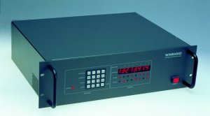
The WiNRADiO WA-811 Antenna Distribution System features 4 antenna inputs and 8 receiver outputs,
and consists of antenna matrix switches, preamplifiers with an extremely high third order intercept point,
and a combination of suitable filters. Fully integrated to achieve the
best possible performance over a wide frequency range, this system is eminently
suitable for government, defence, law enforcement and other demanding high-end
applications.
The unit can be operated autonomously via
a control panel, or remotely via an RS-232 link using Windows-based
PC-resident software with an easy-to-use graphical user interface.
These units can be used with any third-party equipment,
and are particularly suitable for WiNRADiO MS-8000-series
Multichannel Surveillance and Monitoring Systems,
for which they provide user-transparent, fully automatic antenna switching.
|
The antenna inputs are configured as follows:
|
Antenna 1 |
0.15 - 30 MHz |
|
Antenna 2 |
30 -100 MHz |
|
Antenna 3 |
100-1500 MHz |
|
Antenna 4 |
100-1500 MHz |
|
The frequency boundaries can be customized to meet individual customer
specifications. For each antenna input, an 18dB switchable attenuator
and a band-stop filter for broadcast frequencies can be used.
The attenuators and filters can be engaged for each antenna independently,
either directly via the front panel or remotely via the serial port.
|
The unit also contains the following user-switchable filters, in addition
to the fixed band preselector filters. These are used to reject broadcast
frequencies:
|
Ant. 1 Filter |
0.515-1.610 MHz |
|
Ant. 2 Filter |
88-108 MHz |
|
Ant. 3 Filter |
88-108 MHz |
|
Ant. 4 Filter |
88-108 MHz |
|
The unit also contains power supplies for external antenna preamplifiers
(+12V is applied to the antenna leads). These voltages are normally switched
off by default, and can be selectively enabled/disabled
in remote operation mode.
|
|
Front View

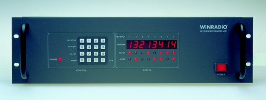
The front panel of the WA-811 unit is divided into a keypad area and
the status display. The keypad is used to enter the matrix configuration
(which receiver is connected to which antenna), to switch on/off the attenuators
and band-stop filters, and to enable/disable remote control.
|
|
Rear View

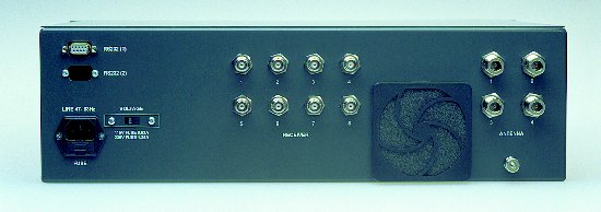
The antennas are connected using N-type connectors at the rear of the unit.
The receivers are connected via BNC connectors. Connecting to the RS-232 serial port
is done via a standard 9-pin connector. An optional second RS-232 port may be
installed by special requirement. (This is usually used in high-reliability
redundancy systems where the second RS-232 port is connected to a back-up computer
equipment.)
|
|
Remote Operation
In remote operation mode, the unit will accept commands from the host computer
and continue showing the current settings on the front panel status display.
The unit can be controlled and its status interrogated via the serial interface,
using a set of low level commands.
|

|
|
Control Software
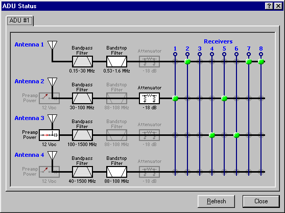
For easy control of the unit from a PC under Windows, virtual control panel
software is available, and supplied as part of the package. This software has
a self-explanatory graphical user interface which makes it possible for the
operator to observe what is happening inside the unit:

Virtual control panel of WA-811
The status of the antenna matrix is observed in a grid of antenna inputs and
receiver outputs, and is easily changed by clicking on the intersecting lines.
The status of filters and attenuators is shown by highlighting of the active
attenuators or filters, and changed by simply clicking on the corresponding
function blocks. Note also that power for the external antenna preamplifiers
can be controlled from here, by clicking on the associated power supply blocks.
|

|
|
Technical Specifications
|
|
Configuration
|
4 inputs / 8 outputs
Fully non-blocking
|
|
Gain
|
0 dB typ.
|
|
Frequency range
|
0.15 MHz to 1500 MHz
|
|
Impedance
|
50 ohm (all inputs and outputs)
|
|
Max input level
|
+20 dBm for no damage
|
|
Gain compression point
|
|
Antenna Input |
Frequency |
1dB GPC |
| 1 |
27 MHz
|
+27 dBm
|
| 2 |
50 MHz
|
+20 dBm |
| 3 |
800 MHz
|
+1 dBm
|
| 4 |
1400 MHz
|
+5 dBm
|
|
|
Second and third order intercept points (typical values)
|
|
Antenna Input |
Frequency |
IP2 |
IP3 |
| 1 |
2 MHz
|
+85 dBm
|
+37 dBm
|
| 2 |
50 MHz
|
+65 dBm
|
+30 dBm
|
| 3 |
800 MHz
|
+53 dBm
|
+11 dBm
|
| 4 |
1400 MHz |
+53 dBm
|
+15 dBm |
|
|
Dynamic range (typical values)
|
| Antenna Input |
Frequency |
Dynamic range |
| 1 |
2 MHz
|
111 dB
|
| 2 |
50 MHz |
107 dB |
| 3 |
800 MHz
|
97 dB
|
| 4 |
1400 MHz |
97 dB |
|
Output-to-output isolation
(typical values)
|
| Frequency |
Isolation |
| 20 MHz |
87 dB
|
| 100 MHz
|
75 dB |
| 400 MHz
|
67 dB |
| 1490 MHz
|
65 dB |
|
Input-to-output isolation
(typical values)
|
| Frequency |
Isolation |
| 20 MHz |
60dB
|
| 100 MHz
|
46 dB |
| 400 MHz
|
37 dB |
| 1490 MHz
|
35 dB |
|
|
Power
|
120/240 VAC, selectable
|
|
Dimensions
|
Width: 19" rack
Height: 3RU (5.25" = 133 mm)
Depth: 14.4"(365 mm)
|
|
Weight
|
19.5 lb (8.8 kg)
|
Specifications are subject to change without notice due to continuous product development and improvement.

|
Please use our Rapid Response Form to register your interest in this product, or to request more information.
|
|

|
